

How UART Works?
In UART Serial Communication, the data is transmitted asynchronously i.e. there is no clock or other timing signal involved between the sender and receiver. Instead of clock signal, UART uses some special bits called Start and Stop bits.
These bits are added to the actual data packet at the beginning and end respectively. These additional bits allows the receiving UART to identify the actual data.
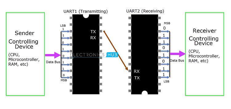
The image above shows a typical UART connection. The transmitting UART receives data from the controlling device through the data bus. The controlling device can be anything like a CPU of a microprocessor or a microcontroller, memory unit like a RAM or ROM, etc. The data received by the transmitting UART from the data bus is parallel data.
To this data, the UART adds Start, Parity and Stop bits in order to convert it into a data packet. The data packet is then converted from parallel to serial with the help of shift register and is transmitted bit – by – bit from the TX pin.
The receiving UART receives this serial data at the RX pin and detects the actual data by identifying the start and stop bits. Parity bit is used to check the integrity of the data.
Up on separating the start, parity and stop bits from the data packet, the data is converted to parallel data with the help of shift register. This parallel data is sent to the controller at the receiving end through a data bus.
Structure of Data Packet or Frame
The data in UART serial communication is organised in to blocks called Packets or Frames. The structure of a typical UART Data Packet or the standard framing of the data is shown in the following image.
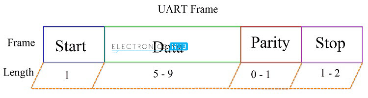
Let us see about each piece of the frame.
Start Bit: Start bit is a synchronisation bit that is added before the actual data. Start bit marks the beginning of the data packet. Usually, an idle data line i.e. when the data transmission line is not transmitting any data, it is held at a high voltage level (1).
In order to start the data transfer, the transmitting UART pulls the data line from high voltage level to low voltage level (from 1 to 0). The receiving UART detects this change from high to low on the data line and begins reading the actual data. Usually, there is only one start bit.
Stop Bit: The Stop Bit, as the name suggests, marks the end of the data packet. It is usually two bits long but often only on bit is used. In order to end the transmission, the UART maintains the data line at high voltage (1).
Parity Bit: Parity allows the receiver to check whether the received data is correct or not. Parity is a low – level error checking system and comes in two varieties: Even Parity and Odd Parity. Parity bit is optional and it is actually not that widely used.
Data Bits: Data bits are the actual data being transmitted from sender to receiver. The length of the data frame can be anywhere between 5 and 9 (9 bits if parity is not used and only 8 bits if parity is used). Usually, the LSB is the first bit of data to be transmitted (unless otherwise specified).
Rules of UART
As mentioned earlier, there is no clock signal in UART and the transmitter and receiver must agree on some rules of serial communication for error free transfer of data. The rules include:
- Synchronisation Bits (Start and Stop bits)
- Parity Bit
- Data Bits and
- Baud Rate
We have seen about synchronisation bits, parity bit and data bits. Another important parameter is the Baud Rate.
Baud Rate: The speed at which the data is transmitted is mentioned using Baud Rate. Both the transmitting UART and Receiving UART must agree on the Baud Rate for a successful data transmission.
Baud Rate is measured in bits per second. Some of the standard baud rates are 4800 bps, 9600 bps, 19200 bps, 115200 bps etc. Out of these 9600 bps baud rate is the most commonly used one.
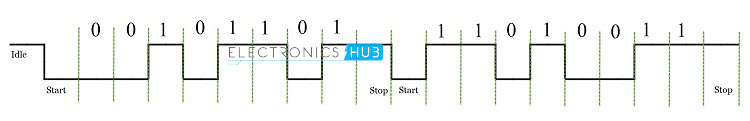
Let us see an example data frame where two blocks of data i.e. 00101101 and 11010011 must be transmitted. The format of the frame is 9600 8N1 i.e. 9600 bps with 8 bits of data, no parity and 1 stop bit. In this example, we haven’t used the parity bit.

Advantages of UART
- Requires only two wires for full duplex data transmission (apart from the power lines).
- No need for clock or any other timing signal.
- Parity bit ensures basic error checking is integrated in to the data packet frame.
Disadvantages of UART
- Size of the data in the frame is limited.
- Speed for data transfer is less compared to parallel communication.
- Transmitter and receiver must agree to the rules of transmission and appropriate baud rate must be selected.