The nonsynchronous rectifying type, which has been in use for years, features a simple circuit for a switching regulator, with an efficiency barely topping 80%. Subsequently, the appearance of battery-powered applications drawing relatively large power and requiring high efficiency, such as notebook PCs, has led to the development of a succession of ICs for synchronous rectifying switching regulators capable of delivering superior efficiency. Aided by innovations that have facilitated the design of the synchronous rectifying type requiring complex control and circuitry, this type of switching regulator, offering a maximum efficiency close to 95%, has gradually become predominant.
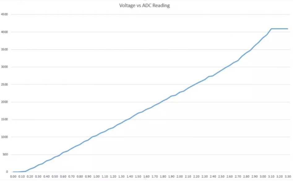
ADC is Non-linear Ideally, you would expect a linear behavior when using the ESP32 ADC pins. However, that doesn’t happen. What you’ll get is behavior as shown in the following chart:
typical inputs are VP or VN or others 16 pins so The ESP32 supports measurements in 18 different channels The voltage measured is then assigned to a value between 0 and 4095(12 bits), in which 0 V corresponds to 0, and 3.3 V corresponds to 4095. Any voltage between 0 V and 3.3 V will be given the corresponding value in between.
the easiest way to use adc is
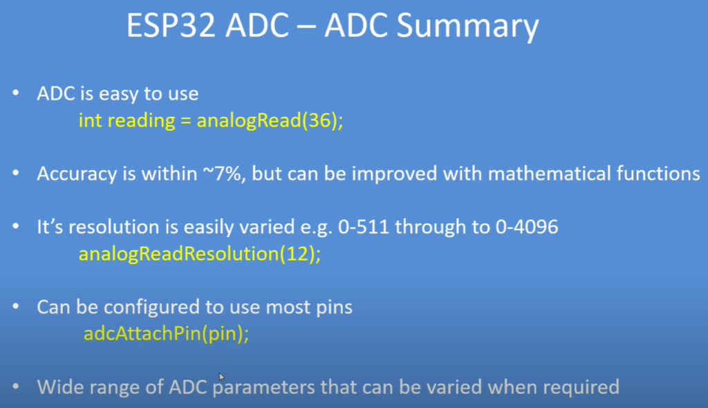
analogRead(GPIO);
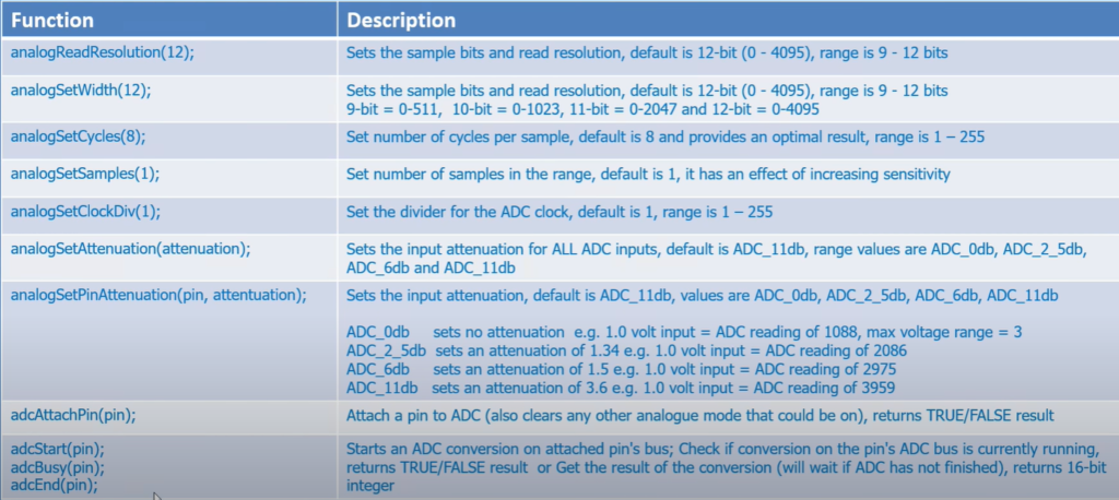
analogReadResolution(resolution)//set the sample bits and resolution. It can be a value between 9 (0 – 511) and 12 bits (0 – 4095). Default is 12-bit resolution.
but actually there are other useful functions
analogSetWidth(width): set the sample bits and resolution. It can be a value between 9 (0 – 511) and 12 bits (0 – 4095). Default is 12-bit resolution.
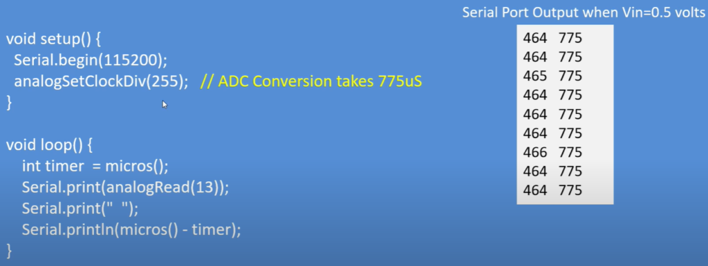
analogSetCycles(cycles): set the number of cycles per sample. Default is 8. Range: 1 to 255.
analogSetSamples(samples): set the number of samples in the range. Default is 1 sample. It has an effect of increasing sensitivity.
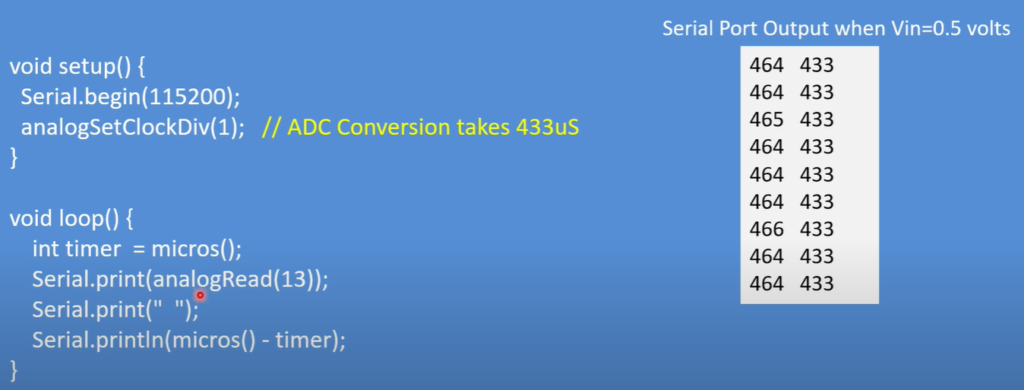
analogSetClockDiv(attenuation): set the divider for the ADC clock. Default is 1. Range: 1 to 255.
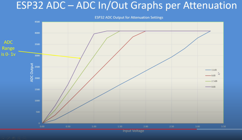
analogSetAttenuation(attenuation): sets the input attenuation for all ADC pins. Default is ADC_11db. Accepted values:
ADC_0db: sets no attenuation (1V input = ADC reading of 1088).
ADC_2_5db: sets an attenuation of 1.34 (1V input = ADC reading of 2086).
ADC_6db: sets an attenuation of 1.5 (1V input = ADC reading of 2975).
ADC_11db: sets an attenuation of 3.6 (1V input = ADC reading of 3959).
analogSetPinAttenuation(pin, attenuation): sets the input attenuation for the specified pin. The default is ADC_11db. Attenuation values are the same from previous function.
adcAttachPin(pin): Attach a pin to ADC (also clears any other analog mode that could be on). Returns TRUE or FALSE result.
adcStart(pin), adcBusy(pin) and adcEnd(pin): starts an ADC convertion on attached pin’s bus. Check if conversion on the pin’s ADC bus is currently running (returns TRUE or FALSE). Get the result of the conversion: returns 16-bit integer.
DAC
there are two DAC GPIO in esp32 GPIO25 and GPIO26
#define DAC1 25

void setup() {
  Serial.begin(115200);

}

void loop() { // Generate a Sine wave
  int Value = 255; //255= 3.3V 128=1.65V

  dacWrite(DAC1, Value);
  delay(1000);
}